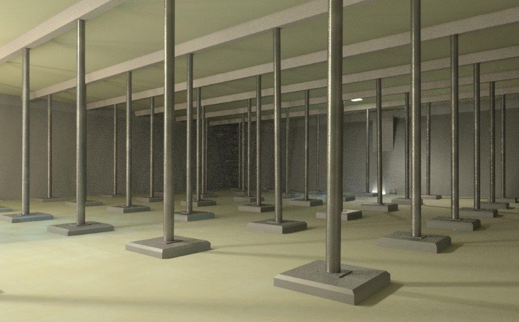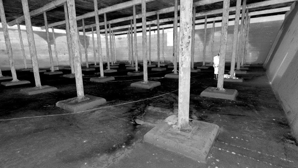
Mason Clark Associates were initially commissioned to undertake a measured survey and an intrusive condition survey of the internals of the 4.1 Megalitres 1920s reservoir, in order to provide a specification for repairs and feasibility of major alteration works to improve network resilience.
A 3D laser scan of the internal elements inside the reservoir and associated construction elements including ancillary equipment, weirs, washout sumps and pipe invert levels, was undertaken and generated into a point cloud from which a fully measurable Revit BIM model was created.
The BIM model was passed on as a deliverable to the asset owner who used the accurate 3D model in further hydraulic modelling scenarios for fluid movement to determine areas of intense mixing and dead spots.
As part of the condition survey MCA investigated, managed and interpreted to our client the range of testing required for the condition survey. Destructively, 150mm diameter cores and 25mm drill holes were undertaken. Visual and non-destructive investigation to the cast iron columns and concrete elements generally; including delamination, carbonation, concrete cover, corrosion potential, crack movement, estimating the strength of in-situ concrete with rebound hammers.
A repair scheme was devised to prevent further carbonation of the concrete in the roof slab. A designed application of a cementitious coating to the soffit of the concrete slab in affected areas, acts as a protective barrier to prevent water vapor from reaching the reinforcement. Spalled areas of concrete, patch repaired using a submersion in water mortar. Areas of rust-stained concrete roof slab were broken out to replace the reinforcement.
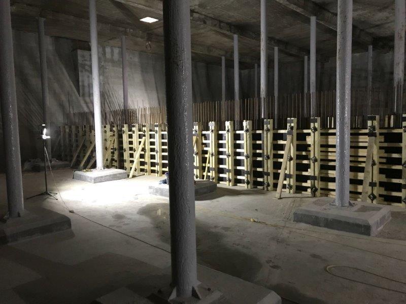
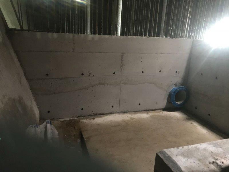
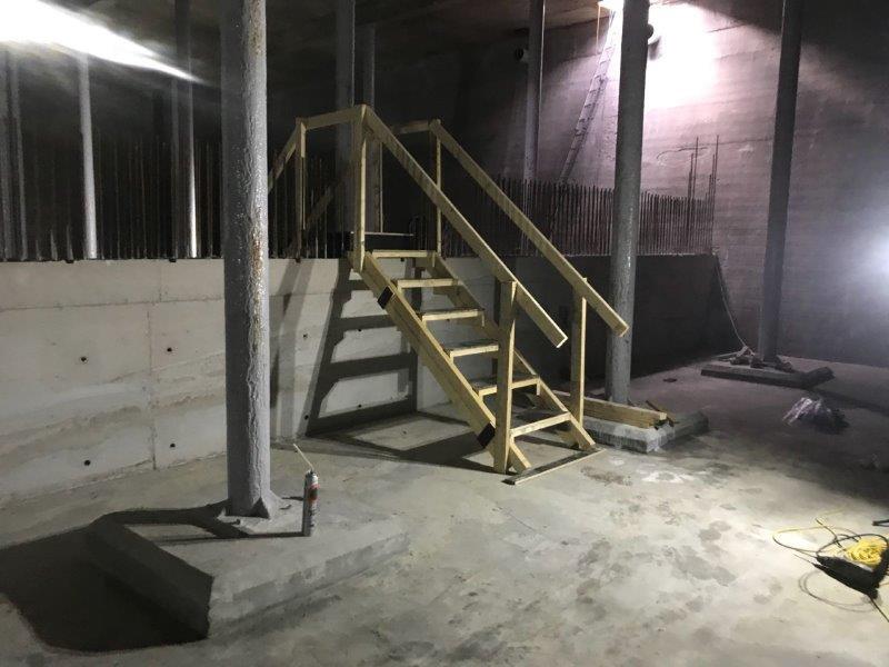
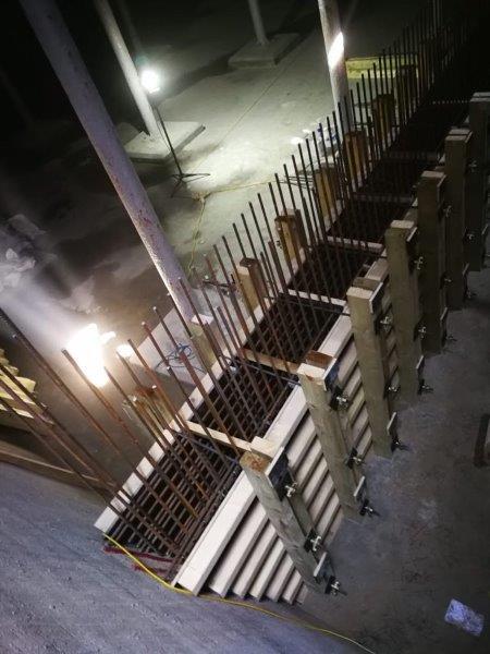
Mason Clark Associates were further involved upon being novated by the winning contractor to provide the permanent works design for the new full height concrete dividing wall, in order to create two separate compartments. This comprised of a 400mm thick cantilever retaining wall, designed to not exceed existing the load distribution that the floor slab had been previously calculated to withstand. In addition, a small valve chamber was formed at one end to house T-pieces of pipework and a upper grating floor and staircase for access.
